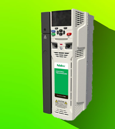
Pump Drive F600
Simple, reliable flow control
Applications involving the flow of water demand extreme reliability and low energy consumption. Control Techniques’ F600 drive, part of the newly introduced Specialist series of industry-specific drive technologies, builds on our company’s five decades of drives expertise, delivering precise, dependable flow control.
Açıklama
The perfect mix of application-specific features developed into a single solution
Speaks your languageThe F600 drive is tuned to suit your every need, optimised for minimal setup time yet sacrificing none of the flexibility. Whatever the challenge, our dedicated approach to clear parameter naming and structuring ensures we not only have the answers, but in a format you’ll understand. |
|
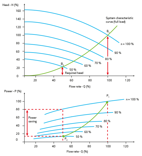
Energy savings, unlocking the potentialOn average, 85% of a pump’s life-cycle cost is attributed to its energy consumption, therefore, optimising the energy usage can mean a significant reduction in the total cost of ownership. The F600 drive thrives on delivering more efficient ways of operating your variable torque application. You’ll see the benefits in reduced running costs and lower energy requirements. |
|
Total controlThe F600 can also control the most efficient motors available, meeting IE5 efficiency levels, such as the Nidec Leroy Somer Dyneo+ hybrid permanent-magnet motor. With all of this combined, the F600 is your best choice to save you money every day. |
|
Engineered for your applicationThe F600 Pump Drive offers a host of dedicated features including dry-run prevention, pipe fill, pump cleaning, over-cycling protection and level switch control. A range of different control modes covering single pumps and also different parallel pump configurations make Control Techniques’ F600 a truly versatile solution. |
|
Free 5 year warrantyTo share our confidence in the reliability of Control Techniques, drives in the F600 range are eligible for Control Techniques’ extended warranty, at no extra cost. |
- Fire mode allows the drive to disable all trips and to continue to run uninterrupted during emergency events if the application requires
- Energy usage is optimised whereby the assist pumps are only enabled when demand reaches sufficient levels.
- Assist pumps are used alternately to apply uniform wear and increase pump availability.
- Over-cycling protection for assist pumps to control the number of starts and stops per hour.
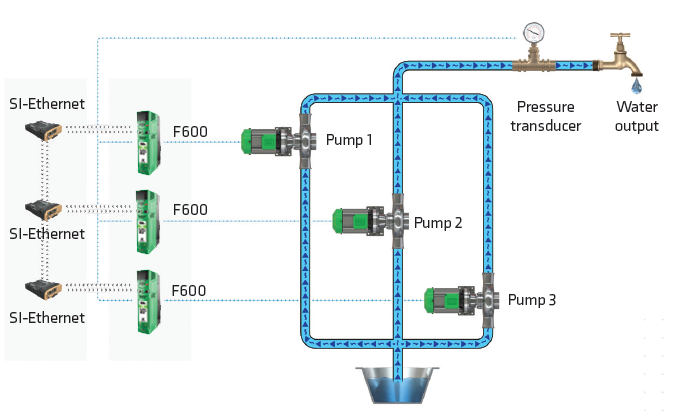
- The Multi-leader drive configuration provides redundancy and removes the need for a PLC
- The “lead” drive is automatically cycled to apply uniform wear
- If the “lead” drive loses its transducer, it can access the transducer feedback from another F600 in the system over Ethernet
- Dynamic re-selection of “lead” pump if a pump is taken out of service or develops a fault
Features
Unmatched total cost of ownership
With innovative protective features and extended equipment life
The F600 has comprehensive pump and motor protection features which minimise unplanned downtime, improving overall effectiveness and guaranteeing better value for money. Bring true resilience to your application and easily ride-through component failures.
Automatic Error Recovery
In the unlikely event of detecting an error with your pump, the F600 has the ability to dynamically recover and resume normal operation.
Limit Protection
If the feedback exceeds the limits defined for your application, the F600 has the ability to raise an alarm or stop the drive to protect your equipment and preserve its lifetime.
Transducer Loss Protection
In the event of losing connection to the transducer, the F600 can stop, continue to run at a fixed speed or ignore the fault depending on the application requirements.
Fire mode
Fire mode allows the drive to disable all trips and to continue to run uninterrupted during emergency events if the application requires.
Save on energy through a wide range of energy features
The F600 is 98% efficient, meaning very little energy is lost in power conversion.
Even more, the real savings potential gets unlocked by the F600’s built-in features that can further reduce energy consumption:
Low load savings
The F600 helps maximise energy savings when demand is low. Activing Control Techniques’ leading-edge Low Load Power Saving function, the drive dynamically reduces the voltage applied to reduce losses in the motor and make the system more efficient.
Sleep mode
When demand falls below a specified set-point the drive will automatically enter sleep mode and restart itself once demand rises above the set-point. Not only does this greatly reduce the amount of energy consumed, it also saves on equipment wear to preserve its lifetime.
The F600 features optimised control for your flow applications
Pipe fill
Prevent spikes in pressure at start-up using a controlled ramp, to protect your piping system and the pump itself.
Dry-run prevention
Prevent the pump running dry by checking the load against a threshold; with flexible configurations to dynamically adjust output, set an alarm or stop the drive.
Over-cycling protection
Optimise drive, motor and pump sizing, and regulate pump wear by limiting the number of start-stops per hour. Flexible configurations allow to dynamically alter cycling reference limits, set an alarm or stop the drive when a limit is reached.
No-flow detection
Where there is no-flow or low-flow, the F600 drive can automatically enter sleep mode to save energy, based on the feedback of a pulsed flow transducer, or triggered by a flow switch, or detected by the software alone.
Cleaning
Live, continuous monitoring of the system is used to trigger an automatic drive-based cleansing cycle to clear the pump impeller and help avoid maintenance costs on cleaning pump blockages.
Level switch control
Level switches provide critical protection for tanks in the event of the level reaching a “high” switch, whereby the pump is stopped, or a “low” switch, whereby the pump is started, to ensure pumping within tank levels.
Pump Control Modes | Flexible support for every system
Single pump
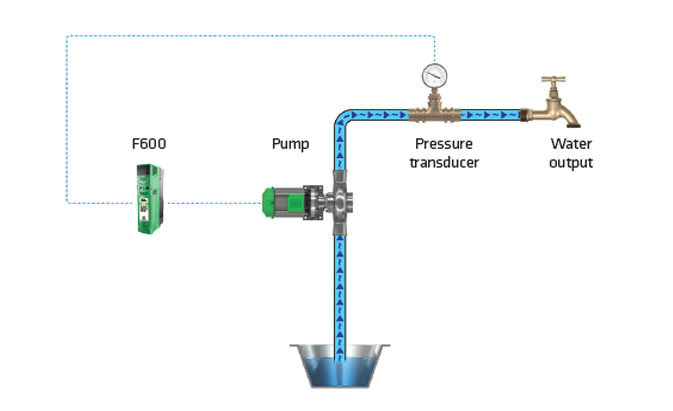
Control Techniques’ Single Pump mode is an effective and versatile variable speed control solution for maintaining a constant set-point in a single pump configuration.
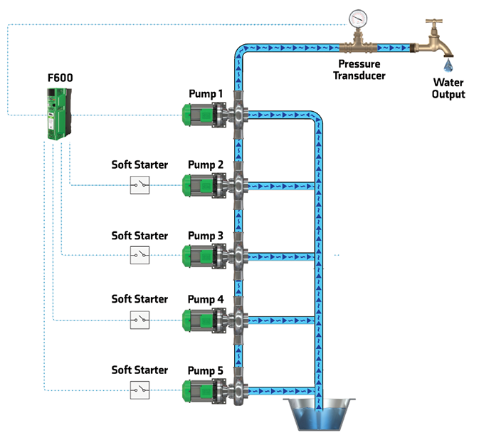
Cascade
Cascade mode allows the F600 to operate with up to 4 assist pumps to aid the primary pump when required.
Multi-leader
Complete control of your application with up to 3 x F600 drives and maximum energy savings with these variable frequency drives running parallel.
Free Standing Drive Range
Ready to use pre-engineered high power drives
Highly efficient pre-engineered motor control system
Control Techniques’ Free Standing Drive optimises motor energy efficiency and comes ready to use, pre-assembled in its own industry-standard cabinet with all necessary system components included. The Pump Drive F600’s Free Standing Drive variant complements and extends the product range, while having all of the core product’s capabilities and features.
Light weight, but no light weight!
The F600 is also available with Control Techniques’ largest frame, which not only offers 500 kW of power in a single module, but at 130 kg is up to 60 kg lighter than competitor drives. Its small footprint and pre-engineered accessories make it easy to install or retrofit in industry-standard cubicles.
No extra engineering required
The Free Standing Drive fits a small footprint, and it’s easy to integrate with common cubicles, including as standard: load switch, fuses, fan, line and sharing chokes and cabling. The cabinet can also come with a doormounted HMI with Real-Time Clock, for easy set-up and maintenance.
Thanks to the dedicated online configurator, getting a quote and ordering is as simple as can be. Even more, we can ship your Free Standing Drive to you at very short lead times, saving weeks on typical industry standards.
- IP20 / NEMA1 / UL TYPE 1 *UL open class as standard, additional kit needed to achieve Type 1
- IP65 / NEMA4 / UL TYPE 12 rating is achieved on the rear of the drive when through panel mounted
- *Frame size 9D, 9E, 10D and 10E achieve IP55 / NEMA 4 / UL Type 12
- Ambient temperature -20 °C to 40 °C (-4 °F to 104 °F) as standard. Up to 55 °C (131 °F) with derating
- Humidity 95 % maximum (non-condensing) at 40 °C (104 °F)
- Altitude: 0 to 3000 m (9900 ft), derate 1 % per 100 m (330 ft) between 1000 m (3300 ft) and 3000 m (9900 ft)
- Random Vibration Tested in accordance with IEC 60068-2-64
- Bump Tested in accordance with IEC 60068-2-29
- Sinusoidal Vibration Tested in accordance with IEC 60068-2-6
- Mechanical Shock Tested in accordance with IEC 60068-2-29
- Storage temperature -40 °C to 55 °C (-40 °F to 131 °F) or up to 70 °C (158 °F) for short-term storage
- Electromagnetic Immunity complies with EN 61800-3 and EN 61000-6-2
- With onboard EMC filter, emissions comply with EN 61800-3 (category C3)
- EN 61000-6-3 and EN 61000-6-4 with optional footprint EMC filter
- IEC 60146-1-1 Supply conditions (category C1 or C2 depending on rating)
- IEC 61800-5-1 (Electrical Safety)
- IEC 61131-2 I/O
- EN 61000-3-12 with optional line reactor
- UL 508C (Electrical Safety)
Specifications
Pump Drive F600 ratings guide
| 200/240 Vac ±10% | |||
| Drive | Normal Duty | ||
| Max continuous current (A) |
Motor shaft |
Motor shaft power (hp) |
|
| F600-03200066A10 | 6.6 | 1.1 | 1.5 |
| F600-03200080A10 | 8 | 1.5 | 2 |
| F600-03200110A10 | 11 | 2.2 | 3 |
| F600-03200127A10 | 12.7 | 3 | 3 |
| F600-04200180A10 | 18 | 4 | 5 |
| F600-04200250A10 | 25 | 5.5 | 7.5 |
| F600-05200300A10 | 30 | 7.5 | 10 |
| F600-06200500A10 | 50 | 11 | 15 |
| F600-06200580A10 | 58 | 15 | 20 |
| F600-07200750A10 | 75 | 18.5 | 25 |
| F600-07200940A10 | 94 | 22 | 30 |
| F600-07201170A10 | 117 | 30 | 40 |
| F600-08201490A10 | 149 | 37 | 50 |
| F600-08201800A10 | 180 | 45 | 60 |
| F600-09202160A10 | 216 | 55 | 75 |
| F600-09202660A10 | 266 | 75 | 100 |
| F600-09202160E10 | 216 | 55 | 75 |
| F600-09202660E10 | 266 | 75 | 100 |
| F600-10203250E10 | 325 | 90 | 125 |
| F600-10203600E10 | 360 | 110 | 150 |
| 380/480 Vac ±10% | |||
| Drive | Normal Duty | ||
| Max continuous current (A) |
Motor shaft power (kW) |
Motor shaft power (hp) |
|
| F600-03400034A10 | 3.4 | 1.1 | 1.5 |
| F600-03400045A10 | 4.5 | 1.5 | 2 |
| F600-03400062A10 | 6.2 | 2.2 | 3 |
| F600-03400077A10 | 7.7 | 3 | 5 |
| F600-03400104A10 | 10.4 | 4 | 5 |
| F600-03400123A10 | 12.3 | 5.5 | 7.5 |
| F600-04400185A10 | 18.5 | 7.5 | 10 |
| F600-04400240A10 | 24 | 11 | 15 |
| F600-05400300A10 | 30 | 15 | 20 |
| F600-06400380A10 | 38 | 18.5 | 25 |
| F600-06400480A10 | 48 | 22 | 30 |
| F600-06400630A10 | 63 | 30 | 40 |
| F600-07400790A10 | 79 | 37 | 50 |
| F600-07400940A10 | 94 | 45 | 60 |
| F600-07401120A10 | 112 | 55 | 75 |
| F600-08401550A10 | 155 | 75 | 100 |
| F600-08401840A10 | 184 | 90 | 125 |
| F600-09402210A10 | 221 | 110 | 150 |
| F600-09402660A10 | 266 | 132 | 200 |
| F600-09402210E10 | 221 | 110 | 150 |
| F600-09402660E10 | 266 | 132 | 200 |
| F600-10403200E10 | 320 | 160 | 250 |
| F600-10403610E10 | 361 | 200 | 300 |
| F600-11404370E10 | 437 | 225 | 350 |
| F600-11404870E10 | 487 | 250 | 400 |
| F600-11405070E10 | 507 | 280 | 450 |
| 380/480 Vac ±10% | |||
| Drive | Normal Duty | ||
| Max continuous current (A) |
Motor shaft power (kW) |
Motor shaft power (hp) |
|
| F600-12404800TU0 | 608 | 315 | 500 |
| F600-12405660TU0 | 660 | 355 | 550 |
| F600-12406600TU0 | 755 | 400 | 650 |
| F600-12407200TU0 | 865 | 500 | 700 |
| 500/575 Vac ±10% | |||
| Drive | Normal Duty | ||
| Max continuous current (A) |
Motor shaft power (kW) |
Motor shaft power (hp) |
|
| F600-05500039A10 | 3.9 | 2.2 | 3 |
| F600-05500061A10 | 6.1 | 4 | 5 |
| F600-05500100A10 | 10 | 5.5 | 7.5 |
| F600-06500120A10 | 12 | 7.5 | 10 |
| F600-06500170A10 | 17 | 11 | 15 |
| F600-06500220A10 | 22 | 15 | 20 |
| F600-06500270A10 | 27 | 18.5 | 25 |
| F600-06500340A10 | 34 | 22 | 30 |
| F600-06500430A10 | 43 | 30 | 40 |
| F600-07500530A10 | 53 | 37 | 50 |
| F600-07500730A10 | 73 | 45 | 60 |
| F600-08500860A10 | 86 | 55 | 75 |
| F600-08501080A10 | 108 | 75 | 100 |
| F600-09501250A10 | 125 | 90 | 125 |
| F600-09501550A10 | 155 | 110 | 150 |
| F600-09501250E10 | 125 | 90 | 125 |
| F600-09501500E10 | 150 | 110 | 150 |
| F600-10502000E10 | 200 | 130 | 200 |
| F600-11502480E10 | 248 | 175 | 250 |
| F600-11502880E10 | 288 | 225 | 300 |
| F600-11503150E10 | 315 | 250 | 350 |
| 500/690 Vac ±10% | |||
| Drive | Normal Duty | ||
| Max continuous current (A) |
Motor shaft power (kW) |
Motor shaft power (hp) |
|
| F600-07600230A10 | 23 | 18.5 | 25 |
| F600-07600300A10 | 30 | 22 | 30 |
| F600-07600360A10 | 36 | 30 | 40 |
| F600-07600460A10 | 46 | 37 | 50 |
| F600-07600520A10 | 52 | 45 | 60 |
| F600-07600730A10 | 73 | 55 | 75 |
| F600-08600860A10 | 86 | 75 | 100 |
| F600-08601080A10 | 108 | 90 | 125 |
| F600-09601250A10 | 125 | 110 | 150 |
| F600-09601500A10 | 150 | 132 | 175 |
| F600-09601250E10 | 125 | 110 | 150 |
| F600-09601550E10 | 155 | 132 | 175 |
| F600-10601720E10 | 172 | 160 | 200 |
| F600-10601970E10 | 197 | 185 | 250 |
| F600-11602250E10 | 225 | 200 | 250 |
| F600-11602750E10 | 275 | 250 | 300 |
| F600-11603050E10 | 305 | 280 | 400 |
Normal duty operation only
Suitable for pump applications, with a current overload requirement of 110% for 60 s*.
Conformance
Dimensions
| Frame size | Dimensions | Weight | |
| mm (HxWxD) | in (HxWxD) | kg (lb) | |
| 3 | 382 x 83 x 200 | 15.0 x 3.3 x 7.9 | 4.5 (9.9) |
| 4 | 391 x 124 x 200 | 15.4 x 4.9 x 7.9 | 6.5 (14.3) |
| 5 | 391 x 143 x 200 | 15.4 x 5.6 x 7.6 | 7.4 (16.3) |
| 6 | 391 x 210 x 227 | 15.4 x 8.3 x 8.9 | 14 (30.9) |
| 7 | 557 x 270 x 280 | 21.9 x 10.6 x 11.0 | 28 (61.7) |
| 8 | 803 x 310 x 290 | 31.6 x 12.2 x 11.4 | 50 (110.2) |
| 9A | 1108 x 310 x 290 | 43.6 x 12.2 x 11.4 | 66.5 (146.6) |
| 9E/10E | 1069 x 310 x 290 | 42.1 x 12.2 x 11.4 | 46 (101.4) |
| 9D/10D |
Rectifier |
Rectifier 15.8 x 12.2 x 11.4 ———————– Inverter 30.4 x 12.2 x 11.4 |
|
| 11E | 1242 x 310 x 312 | 48.9 x 12.2 x 12.3 | 63 (138.9) |
| 12T | 1750 x 295 x 526 | 68.9 x 11.6 x 20.7 | 130 (287) |
*For more detailed information please see technical documents.
Eklentiler
Keypads
 |
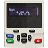
KI-HOA Keypad RTC (Supplied as standard*) The KI-HOA Keypad RTC provides Hand-Off-Auto control. The display presents up to four lines of real text with multilanguage translation, enhancing clarity and increasing ease of use. A battery operated real-time clock allows scheduling of run and off periods and adds accurate time stamping to diagnostics to aid rapid fault resolution. |
 |
Remote HOA Keypad RTC Remote mountable keypad, allowing flexible mounting on the outside of a panel (meets IP54/NEMA 12). The keypad offers Hand-Off-Auto control and can present up to four lines of real text with multi language translation, enhancing clarity and increasing ease of use. Battery operated real-time clock allows scheduling of run and off periods and adds accurate time stamping to logged events, aiding diagnostics. |
|
|
KI-485 Adaptor This adaptor can be fit in place of the drive keypad and provides additional ports to communicate via RS485. The adaptor is commonly used for programming the drive. |

System Integration Modules – Communications
 |
SI-POWERLINK Connects Unidrive, Commander, Digitax and the Pump Drive families to all POWERLINK networks. SI-POWERLINK serves applications ranging from simple open-loop systems through to those demanding precise motion control. The protocol is based upon standard Ethernet and provides a solution for real-time Industrial Ethernet to satisfy the requirements of industrial automation and process control. |
 |
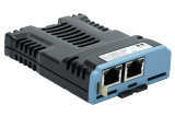
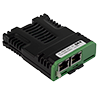
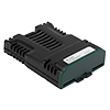
SI-Ethernet External Ethernet module that supports EtherNet/IP and Modbus TCP/IP and has an integrated web server that can generate emails. The module can be used to provide high speed drive access, global connectivity and integration with IT network technologies, such as wireless networking. To use multiple F600 drives in Multi-leader mode in a parallel pump system, each F600 drive must have an SI-Ethernet module fitted. |
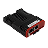 |
SI-EtherCAT SI-EtherCAT allows F600 to connect and interface with EtherCAT networks. |
 |
SI-PROFINET SI-PROFINET allows F600 to communicate and interface with PROFINET PLCs and networks. |
|
|
SI-PROFIBUS PROFIBUS interface module PROFIBUS-DP (Decentralized Peripheral) interface module enables follower connectivity. It is possible to use more than one SI-PROFIBUS or a combination of SI-PROFIBUS and other option modules to add additional functionality such as extended I/O, gateway functionality, or additional PLC features. |
|
|
SI-DeviceNet DeviceNet networking system interface module enables follower connectivity. It is possible to use more than one SIDeviceNet or a combination of SI-DeviceNet and other option modules to provide additional functionality such as extended I/O, gateway functionality, or additional PLC features. |
|
|
SI-CANopen CANopen interface module supporting various profiles, including several drive profiles. |
 |
MCi200 Second processor, providing advanced customisation using standard IEC61131-3 programming languages. |


Additional I/O and NV media cards
|
|
SI-I/O |
 |
Smartcard The optional Smartcard memory device can be used to back-up parameter sets, as well as copying them from one drive to another |
 |
SD Card Adaptor Conversion device that allows an SD card to be inserted into the Smartcard slot, for parameter cloning and application programs |

*For higher cost efficiency,F600 can be supplied without a keypad.
Please specify your preference when ordering.
Yazılım
ntuitive commissioning software
 |
Connect – Commissioning tool Based on Control Techniques’ 25 years’ experience, Connect is our latest drive configuration tool for commissioning, optimizing and monitoring drive/system performance. |
Diagnostics Tool
 |
Diagnostic Tool is a fast and simple tool, which allows users of Control Techniques’ drives to quickly solve any error codes that the drive may show. |
Yüklemeler
BROCHURES |
|||||
USER GUIDES |
|||||
| Title | Issue | File Type |
Size | Lang | |
|---|---|---|---|---|---|
| Pump Drive F600 – User Guide | 1 | 42 MB | EN | Download | |
STEP BY STEP GUIDE |
|||||
| Title | Issue | File Type |
Size | Lang | |
| Pump Drive F600 (Frame sizes 3-11) – Step By Step Guide | 3 | 10 MB | EN | Download | |
OPTION MODULE USER GUIDES |
|||||
| Title | Issue | File Type |
Size | Lang | |
| SI-POWERLINK User Guide | 1 | 4.45 MB | EN | Download | |
SOFTWARE |
|||||
| Title | Issue | File Type |
Size | Lang | |
| Connect Drive Commissioning Software | 2.15.2.02 | zip | 215 MB | EN | Download |
PARAMETER REFERENCE GUIDES |
|||||
| Title | Issue | File Type |
Size | Lang | |
| Pump Drive F600 – Parameter Reference Guide | 4.22.0.0 | zip | 7 MB | EN | Download |
FIRMWARE |
|||||
| Title | Issue | File Type |
Size | Lang | |
| Pump Drive F600 – Firmware | 1.0.0.0 | zip | 512 KB | EN | Download |
ACCESSORIES DATA SHEETS |
|||||
| Title | Issue | File Type |
Size | Lang | |
| Dynamic Braking Resistor Data Sheet | 1 | 333 KB | EN | Download | |
DECLARATION OF CONFORMITY |
|||||
| Title | Issue | File Type |
Size | Lang | |
| Declaration of Conformity under the Machinery Directive – Unidrive M | 1 | 20 KB | EN | Download | |